


Metallic Bellows Feedstock | Temperature, Movement, Cycles and Environment
Select high-temperature expansion-joint sheet or strip from the finished-joint damage mechanisms and approved design basis, not from a maximum-temperature table.

Direct answer: Select the bellows sheet or strip from the calculated bellows metal temperature, movement and cycle spectrum, pressure, atmosphere, corrosion exposure, forming and welding route, and governing design rules. Types 321, 347, and 310 stainless steel, Alloy 625, Alloy 800H/800HT, Alloy 617, and Alloy 230 can all be candidates, but no alloy data sheet establishes expansion-joint life. The finished joint still requires an EJMA, ASME, or EN design basis and project-specific fatigue verification.
A high-temperature metallic expansion joint is not selected by finding the alloy with the highest temperature printed on a data sheet. The bellows is a thin, formed pressure boundary that repeatedly bends at its convolution crowns, sidewalls, and roots. Its material may need to resist oxidation at temperature, but it must also survive imposed displacement, pressure-induced membrane stress, manufacturing strain, weld discontinuities, vibration, and the actual internal and external environments.
That combination changes the procurement question. A 310S sheet may resist oxidation yet be wrong where chloride deposits, severe cyclic strain, or creep governs. Alloy 625 may solve a corrosion problem, but its condition and long-term exposure still matter. Listing 800H, 800HT, 617, or 230 does not create a qualified fatigue curve or an approved design.
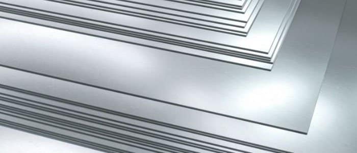
DAXUN manufactures stainless-steel and nickel-alloy sheet, strip, and plate feedstock and performs agreed cutting, slitting, surface preparation, forming-related preparation, heat treatment, and inspection in-house when included in the order. DAXUN does not represent this material supply as the design or certification of a complete expansion joint. The expansion-joint designer or fabricator remains responsible for convolution geometry, pressure capacity, instability, fatigue life, attachment details, anchors, guides, liners, insulation, examination, testing, and code compliance.
Start with the Finished Joint, Not the Alloy Name
The correct material follows from the duty of the finished bellows, not from a generic temperature ranking. Before comparing alloys, define what the expansion joint must absorb, contain, and survive.
A useful design input set includes:
- design, operating, startup, shutdown, cleaning, and upset temperatures;
- calculated bellows metal temperature rather than only process-gas temperature;
- internal and external pressure, full vacuum, pressure transients, and test pressure;
- axial, lateral, and angular movement for each operating case;
- number of full and partial movement cycles, including commissioning and maintenance cycles;
- vibration frequency and amplitude from rotating equipment, pulsation, flow, or acoustic excitation;
- process chemistry, condensates, chlorides, sulfur species, carburizing or nitriding potential, and deposits;
- outdoor, marine, washdown, insulation, and chloride-contamination exposure on the external surface;
- bellows geometry, ply arrangement, nominal thickness, forming method, longitudinal seam, and attachment welds;
- liner, purge, insulation, refractory, and thermal-shield arrangement;
- governing code, EJMA edition, owner specification, inspection class, and documentation requirements.
Expansion-joint bellows are displacement-loaded components. Research shows that cyclic strains can extend beyond the proportional limit and that local plastic strain concentration makes polished-bar fatigue data an unreliable stand-alone predictor of bellows life.[1] The Eleventh Edition EJMA Standards address metallic bellows selection and application through equations and manufacturing practices that a flat-product certificate cannot replace.[2]
The material certificate proves that the ordered sheet or strip met its product specification at the mill. It does not prove that a formed, welded convolution will achieve a specified number of cycles. That claim requires the design method, material fatigue basis, geometry, forming history, weld details, and any required testing to be connected in one approved qualification route.
Which Design Rules Control the Material Decision?
The purchase order must identify the construction route and edition because EJMA, ASME, and EN do different jobs. They should not be cited as interchangeable labels.
ASME B31.3-2024 is a process-piping code. Its structure includes Mandatory Appendix X for metallic bellows expansion joints, while the rest of the piping system remains subject to the applicable piping design, materials, fabrication, examination, testing, and flexibility-analysis rules.[3] EJMA Version 11 is a specialist expansion-joint standard used for bellows selection, application, calculations, manufacturing practices, tolerances, and communication of design requirements.[2]
For European pressure applications, the current British adoption is BS EN 14917:2021+A1:2026. Its scope covers circular metal bellows expansion joints for pressure applications above 0.5 bar and includes design, manufacture, installation, materials, testing, inspection, documentation, and marking.[4] The 2026 amendment matters: an order that merely says “EN 14917” leaves the edition and amendment status unresolved.
These design documents sit above the flat-product specifications:
| Candidate material | Flat-product specification commonly reviewed | Procurement point |
|---|---|---|
| 321, 347, 310/310S stainless steel | ASTM A240/A240M-26 | Confirm exact UNS grade, sheet/strip form, thickness, finish, heat treatment, and any supplementary requirements. |
| Alloy 625, UNS N06625 | ASTM B443-26 | State Grade 1 or Grade 2 where applicable; the condition must match the design-temperature and creep basis. |
| Alloy 800H, UNS N08810; Alloy 800HT, UNS N08811 | ASTM B409-22 | Chemistry, grain size, heat treatment, and certification designation are essential to creep properties. |
| Alloy 617, UNS N06617 | ASTM B168-26 | B168 covers the flat product; it does not itself qualify a bellows fatigue design. |
| Alloy 230, UNS N06230 | ASTM B435-22 | Use only where the drawing, design basis, forming route, and project approval specifically support it. |
ASTM A240/A240M-26 covers stainless plate, sheet, and strip and specifies composition and mechanical requirements for the covered product forms.[5] ASTM B443-26, ASTM B409-22, ASTM B168-26, and ASTM B435-22 establish requirements for their respectively listed nickel-alloy flat products.[6][7][8][15] None of these product specifications calculates convolution stress, spring rate, pressure thrust, squirm pressure, fatigue life, or piping loads.
Gas Temperature Is Not Bellows Metal Temperature
Material screening should use the predicted bellows skin temperature for every operating state. Gas temperature alone can be either too conservative or dangerously non-conservative.
An internal liner can shield the bellows from direct radiant heat and high-velocity flow. External insulation may retain heat and raise the bellows temperature, or an external cover may create a stagnant cavity. Purge gas can cool the annulus. Refractory can reduce radiant exposure but introduce local hot spots when it cracks or shifts. During shutdown, the metal can cool through an acid or water dew point even though the normal operating gas is dry.
The causal chain is important:
process temperature + convection + radiation + liner gap + purge + insulation + ambient conditions -> bellows metal-temperature history -> elastic modulus, yield behavior, oxidation rate, creep rate, corrosion condition, and fatigue response -> material and geometry decision.
A published oxidation temperature is not a bellows design limit. Outokumpu describes 310S as heat- and creep-resisting, with good oxidation resistance in mildly cyclic conditions, and discusses service up to approximately 1050 degrees C (1920 degrees F).[10] This screens clean oxidizing atmospheres; it does not qualify thin 310S bellows for pressure, displacement, and cycles at that temperature.
Special Metals provides typical Alloy 625 tensile, fatigue, creep, and oxidation data but states that they are not specification values.[11] A temperature detached from condition, stress, duration, environment, and geometry cannot become an expansion-joint acceptance criterion.
Cyclic Strain Usually Decides the Bellows Life
For many expansion joints, the dominant mechanical problem is low-cycle fatigue caused by imposed movement. Pressure and temperature alter the stress state, but the movement range sets the repeated bending demand.
When the connected piping expands, the bellows convolutions flex. The highest local strain generally appears around the convolution crown or root rather than being uniformly distributed through the strip. Geometry, thickness, convolution pitch and height, number of convolutions, end restraint, reinforcement, and manufacturing tolerances all affect that concentration. A seemingly small increase in required movement can therefore produce a disproportionate reduction in calculated fatigue life.
Cycle counting must include more than startup and shutdown. Steam-out, decoking, regeneration, cleaning, pressure testing, hot standby, trips, and maintenance movements consume fatigue life. Meaningful partial cycles also matter. Vibration can superimpose a small high-frequency stress on large low-frequency thermal strain; room-temperature elongation does not capture that interaction.
The material comparison should ask:
- What cyclic stress-strain and fatigue basis is accepted by the governing design method?
- Does it apply to the ordered form, temperature, weld condition, and manufacturing route?
- How are forming strain, thinning, heat treatment, and the seam represented?
- Is a type or project-specific fatigue test required outside the established basis?
Becht’s bellows-fatigue work explains why empirical bellows curves and bellows testing have historically been important: plastic strain concentration differentiates an actual convolution from a polished material specimen.[1] Consequently, substituting Alloy 617 for Alloy 625 in the same drawing cannot be justified by comparing tensile strength alone. The new alloy may change elastic modulus, cyclic response, creep relaxation, oxidation, forming springback, weld behavior, and the validity of the fatigue correlation.
Pressure Thrust, Instability, and Piping Loads Cannot Be Separated from Selection
A stronger alloy does not remove pressure thrust or correct an unstable bellows geometry. The expansion joint is part of a piping system, not an isolated flexible coupon.
Internal pressure acting on the effective bellows area creates pressure thrust. In an unrestrained arrangement, anchors or other restraints must react that load. Tied universal, hinged, gimbal, and pressure-balanced arrangements manage loads differently. The designer must also evaluate column instability, in-plane squirm, vacuum behavior, spring forces, nozzle loads, guides, and anchors.
Material strength enters those calculations, but it is only one variable. Increasing thickness may improve pressure capacity while increasing spring rate and movement stress. Adding convolutions may reduce movement per convolution but lengthen the assembly and affect instability. A higher-strength nickel alloy may permit a different geometry, yet its elevated-temperature allowable stress can decline with time-dependent exposure. At creep temperatures, stress relaxation may lower some local stresses while accumulated creep strain and creep-fatigue interaction damage the material.
The 2021 EN 14917 revision explicitly added design in the creep range, and the current 2026 amended edition should be invoked where that route governs.[4] ASME and EJMA calculations must likewise use the applicable material properties, temperature range, and construction rules rather than an unverified extrapolation.

Material Comparison for Sheet and Strip Bellows
The best candidate is the lowest-risk material that satisfies the entire mechanical, thermal, corrosion, fabrication, and code envelope. The following comparison is a screening framework, not a substitution table.
Types 321 and 347 Stainless Steel
321 and 347 are practical stabilized stainless candidates when moderate cost, formability, welding, and resistance to sensitization-related intergranular corrosion are important. Outokumpu identifies 321 as titanium-stabilized and 347 as niobium-stabilized; its 347 guidance specifically lists expansion joints among typical applications and notes usefulness under intermittent heating.[10]
These grades can suit exhaust and moderate-temperature process duties where unstabilized austenitic stainless steel would be vulnerable after welding or sensitizing exposure. They remain susceptible to chloride stress-corrosion cracking when forming or welding stress meets chloride contamination and moisture. EPRI’s maintenance guidance also flags sensitization, pitting, dew-point corrosion, and galvanic effects.[12]
Selection questions include external chloride exposure under insulation, washdown water, cleaning chemicals, process deposits, and shutdown condensation. A stable dry operating atmosphere does not eliminate wet shutdown damage. If chlorides can concentrate on a stressed bellows, a nickel alloy may warrant evaluation even when the normal operating temperature is within the stainless range.
Type 310 and 310S Stainless Steel
310/310S is primarily an oxidation-oriented stainless choice, not an automatic upgrade in fatigue or corrosion resistance. Its high chromium and nickel contents support scale formation in clean high-temperature atmospheres, and 310S is widely considered for furnace and hot-gas hardware.[10]
It becomes less persuasive when the duty includes severe thermal cycling, sulfur- or chlorine-bearing deposits, acid dew-point condensation, large imposed movement, or a creep-governed pressure design. Oxide scale that performs well during an isothermal coupon test may crack or spall during repeated expansion and contraction. A thick scale also consumes a larger fraction of a thin bellows wall than it does of a plate component.
Use 310/310S when the atmosphere, metal temperature, cycle requirement, available fatigue basis, and fabrication route all support it. Do not use the alloy’s oxidation reputation as a substitute for a bellows calculation.
Alloy 625
Alloy 625 is often one of the most broadly applicable candidates when corrosion resistance, formability, weldability, and useful strength must coexist. Its nickel-chromium-molybdenum-niobium composition provides resistance to many aqueous and chloride-bearing environments, and producer literature identifies bellows, ducting, exhaust systems, and steam-line bellows among its applications.[11]
Its broad utility does not make condition irrelevant. The order should identify the ASTM B443-26 grade and condition. Special Metals prefers solution-treated material for optimum creep or rupture resistance above approximately 649 degrees C (1200 degrees F), while fine-grained annealed material may favor fatigue and room-to-intermediate-temperature properties.[11] A creep-oriented condition is not automatically the fatigue-optimum condition.
Alloy 625 should be evaluated carefully where prolonged intermediate-temperature exposure can alter the microstructure or where very high-temperature oxidation dominates. Its corrosion advantage is also environment-specific. It cannot be assumed immune to every molten salt, sulfur-bearing gas, reducing acid, or contaminated deposit.
Alloy 800H and Alloy 800HT
800H and 800HT are creep-oriented candidates for sustained elevated-temperature service, provided the thin-wall forming and fatigue route is specifically qualified. Their value comes from controlled chemistry, high-temperature annealing, and grain-size requirements that improve creep and rupture strength compared with ordinary Alloy 800.[13]
The distinction between N08810 and N08811 is contractual. Special Metals reports tighter carbon and aluminum-plus-titanium controls for 800HT within the 800H composition range, plus a high-temperature treatment; 800H cannot be called 800HT unless it meets the additional requirements.[13] ASTM B409-22 is the flat-product route.[7]
Coarse grain can improve creep strength but may affect forming behavior, surface quality, weld response, and fatigue performance in thin convolutions. The designer should therefore state the required UNS designation, heat treatment, grain-size range, thickness, fatigue basis, and any post-forming treatment. A certificate reading “800 series” is not adequate.
Alloy 617
Alloy 617 is a project-specific high-temperature candidate, not a routine or default bellows alloy. Its nickel-chromium-cobalt-molybdenum chemistry and aluminum addition support high-temperature strength and oxidation resistance, and ASTM B168-26 covers UNS N06617 plate, sheet, and strip.[8]
Those properties make 617 technically interesting when metal temperature and time-dependent strength exceed the comfortable range of more conventional choices. They do not establish convolution fatigue life. A project considering 617 should require the expansion-joint designer to confirm:
- acceptance of N06617 under the governing code and exact edition;
- applicable allowable stress and creep properties at the design temperature and duration;
- a fatigue curve, test basis, or approved analysis appropriate to the formed bellows;
- effects of sheet thickness, grain size, forming reduction, thinning, and heat treatment;
- longitudinal seam and attachment-weld procedures and their fatigue treatment;
- oxidation or corrosion evidence for the real gas and deposit chemistry;
- inspection, leak testing, pressure testing, and any prototype or qualification testing.
Producer data for 617 show strong elevated-temperature behavior, but they remain typical material data, often generated on sheet or plate specimens under stated laboratory conditions.[14] They cannot be converted directly into guaranteed bellows cycles. If the expansion-joint manufacturer does not have an approved N06617 design and manufacturing basis, selecting 617 feedstock may create more qualification work without reducing total project risk.
Alloy 230
Alloy 230 can be considered for specialized very-high-temperature bellows when oxidation resistance, thermal stability, and low-cycle fatigue evidence are valuable, but it requires the same project-specific discipline as 617. Haynes publishes flat-product specifications, forming and welding guidance, oxidation data, and low-cycle fatigue information for UNS N06230, including expansion-bellows applications.[9]
This producer evidence is not a universal finished-joint qualification. Sulfur- or chlorine-bearing streams can change the ranking, and the project must confirm the code route, fatigue basis, weld procedure, availability, and cost. Alloy 230 should remain a deliberately approved candidate.
Why Creep-Fatigue Interaction Changes the Ranking
When the bellows spends significant time in a creep-active temperature range, cycle life and hold time must be assessed together. A start-stop cycle with a long high-temperature hold is not equivalent to a rapid laboratory fatigue cycle.
During a hold, local stresses can relax while creep strain accumulates; cooling then changes the strain distribution again. Oxidation, grain-boundary damage, environmental attack, and weld mismatch can interact. Short-duration tensile performance does not predict thousands of hours of dwell plus movement.
Define the temperature-time histogram, not only maximum temperature. Inputs include annual hours, startup and hot-standby duration, upset exposure, service life, and inspection interval. The accepted method must address time-dependent allowables and fatigue interaction. An alloy, temperature, or geometry outside available rules may require project-specific analysis and testing.
This is another reason Alloy 617 should not be sold as a simple “higher-temperature Alloy 625.” Their chemistry, condition, microstructural response, design allowables, and established bellows experience differ. Material substitution requires a new engineering review.
Forming and Welding Are Part of the Material Specification
Bellows feedstock must be ordered for the intended forming and joining route, because the process changes thickness, residual stress, microstructure, and fatigue-sensitive details. A compliant flat sheet can still produce a poor bellows if its manufacturing route is uncontrolled.
Hydroforming, mechanical forming, roll forming, and welded diaphragm construction impose different strain paths. A formed bellows may thin locally at crowns or sidewalls. Strip width, thickness tolerance, flatness, edge condition, surface defects, grain direction, and consistency between coils can therefore affect the finished geometry. Slitting burrs, scratches, laps, inclusions, and handling damage become more serious as wall thickness decreases.
Longitudinal seam welding adds a fatigue-sensitive feature. The weld procedure must control penetration, reinforcement, undercut, oxidation, contamination, distortion, and heat input. Attachment welds must transfer load without creating an uncontrolled notch at the bellows end. Welding filler, purge practice, cleaning, interpass control, and postweld treatment should follow the governing construction specification and qualified procedure.
Heat treatment cannot be selected by alloy name alone. It may restore ductility, control grain size, develop creep properties, or reduce forming effects, but it can distort thin convolutions. Chemistry, grain size, and annealing are central to 800H/800HT creep properties.[13] Alloy 625 conditions involve a fatigue-versus-creep trade-off.[11] The approved bellows basis must define the condition for 617 and 230.
DAXUN can manufacture the specified sheet, strip, or plate and perform agreed in-house processing against a written order. The customer should not infer that slitting, heat treatment, or surface preparation automatically qualifies the eventual bellows. Traceability must continue from the feedstock heat and processing batch into the expansion-joint manufacturer’s forming, welding, examination, and test records.
Liners, Insulation, and Purge Systems Can Change the Preferred Alloy
Thermal accessories are part of the material decision because they control heat flux, deposits, flow impingement, and condensation. They are not secondary catalog options.
An internal liner can limit direct flow, abrasion, and radiant heat. It must face the correct flow direction and allow thermal growth without damaging the convolutions. It is not a pressure seal and does not isolate the bellows from all process media.
Insulation can reduce heat loss and protect personnel, but poorly located insulation may move the bellows into a hotter metal-temperature regime or trap contaminants against its external surface. Conversely, a hot blanket may be used to keep the bellows above an acid dew point. EPRI identifies maintaining bellows skin temperature above the dew point as a possible response to sulfur-rich gas condensation, illustrating why thermal management and corrosion selection must be solved together.[12]
Purge gas can limit deposits and control annulus chemistry, but reliability matters. The material evaluation should include loss of purge, blocked purge ports, startup before purge, and shutdown condensation. A material that survives only while an ideal auxiliary system operates may be unsuitable for the credible upset case.
Common Failure Modes and What They Reveal
Most premature failures point to a mismatch among material, design assumptions, manufacturing, installation, or operation rather than to alloy chemistry alone. Failure location and morphology should guide the investigation.
| Failure mode | Typical trigger | Evidence to examine | Preventive control |
|---|---|---|---|
| Low-cycle fatigue cracking | Movement or cycles exceed the qualified basis; local thinning or geometry concentration | Crack location at crown/root, movement history, convolution profile, thickness map, design calculation | Recalculate movement cases, verify geometry and thinning, use accepted fatigue basis or testing |
| High-cycle fatigue | Flow-induced vibration, pulsation, rotating equipment, acoustic excitation | Multiple initiation sites, vibration data, piping supports, fretting | Dynamic analysis, support correction, vibration monitoring, design modification |
| Creep-fatigue damage | Long high-temperature dwell plus cyclic movement | Temperature-time history, intergranular damage, deformation, metallography | Time-dependent design, correct material condition, reduced metal temperature, inspection interval |
| Squirm or instability | Pressure exceeds stability capability; missing reinforcement or restraint | Distorted convolution pattern, pressure event, assembly geometry | Verify EJMA/ASME/EN instability and pressure design, test and install correctly |
| Chloride SCC or pitting | Chloride deposits plus moisture and tensile stress | Branched cracks, deposit chemistry, insulation/wash water, shutdown conditions | Control chlorides and moisture; reassess alloy; clean and inspect |
| Dew-point corrosion | Metal cools below water or acid dew point | Localized wall loss, sulfur/chloride deposits, thermal profile | Thermal redesign, insulation/hot blanket/purge, corrosion-resistant material |
| Oxidation or hot corrosion | Metal temperature/chemistry outside material envelope | Scale morphology, metal loss, deposits, temperature evidence | Correct temperature model, liner/purge, environment-qualified alloy |
| Weld-related leakage | Lack of fusion, undercut, contamination, excessive reinforcement, poor attachment detail | PT/RT results, weld macrosection, procedure records, fracture origin | Qualified WPS, controlled fit-up and purge, appropriate NDE and workmanship criteria |
| Installation damage | Torsion, misalignment, premature removal of shipping devices, liner reversal, bad anchors/guides | Site photographs, alignment survey, support condition, movement indicators | Installation procedure, hold points, final system walkdown |
A material upgrade does not correct missing anchors, torsion, or excess movement. A fatigue crack is not proof of a defective alloy; investigation must connect material identity, geometry, manufacturing, installation, operation, and fracture evidence.
How to Verify Feedstock and the Finished Expansion Joint
Verification should form an unbroken evidence chain from the melt to the installed assembly. The scope depends on the code, risk, and project specification, but the following controls are commonly considered.
For sheet and strip feedstock:
- mill test certificate with heat number, exact UNS grade, specification and edition, product form, condition, chemistry, and required mechanical results;
- thickness, width, flatness, edge, surface, and finish inspection;
- grain-size or heat-treatment evidence where required, particularly for creep-strengthened conditions;
- positive material identification when invoked, with a method suitable for the alloy distinction;
- ultrasonic or other volumetric examination only when technically applicable and specified;
- traceability through slitting, cutting, heat treatment, and packing;
- purchaser or third-party witness points where required.
For bellows manufacture and the completed joint:
- approved design calculation to the specified EJMA, ASME, EN, or owner route;
- forming procedure and dimensional records, including convolution profile and local thickness where required;
- qualified welding procedures and personnel, with weld maps and consumable traceability;
- visual examination and surface NDE such as liquid penetrant testing at specified stages;
- radiographic or other volumetric examination where the joint category and construction rules require it;
- leak testing and pressure testing using the specified medium, pressure, duration, and acceptance criteria;
- spring-rate, movement, squirm, or fatigue testing when required by the design or qualification plan;
- final inspection of liners, covers, tie rods, hinges, gimbals, flow arrows, shipping devices, and identification;
- installation records for anchors, guides, alignment, preset, and removal of shipping restraints.
Hydrotest water quality and drying deserve attention for thin stainless or nickel-alloy bellows. Halides left in convolutions can create a later corrosion problem. The project should state water-quality limits, drainage, drying, and preservation requirements rather than relying on a generic “hydrotested” note.
What DAXUN Can Supply for a Bellows Material Package
DAXUN supplies the alloy feedstock and agreed processed material package; the order must preserve the distinction between material manufacturing and complete expansion-joint design. This avoids both a technical gap and an exaggerated scope claim.
DAXUN manufactures stainless-steel and nickel-alloy sheet, strip, and plate to the ordered specification and condition. Agreed in-house services may include slitting, cutting, edge preparation, surface finishing, heat treatment, dimensional inspection, marking, packing, and traceability documentation. The written quotation confirms dimensions, tolerances, examinations, and acceptance criteria.
For projects evaluating Alloy 617, the related Inconel 617 sheet and plate guide explains the flat-product procurement route. That product page does not establish the alloy as a default bellows material; the expansion-joint designer must still approve N06617 for the actual geometry, temperature, fatigue, creep, weld, and code basis.
DAXUN does not claim in this article to perform EJMA calculations, piping flexibility analysis, anchor or guide design, or complete certified expansion-joint fabrication. Those responsibilities should be assigned explicitly to the approved designer and fabricator.
Send the governing code and edition, temperatures, pressure, media, movement, cycles, vibration, geometry, liner or insulation details, alloy candidates, product-form standard, processing, inspection, quantity, and destination for DAXUN material review.
RFQ Checklist for Sheet or Strip Feedstock
A technically reviewable request should connect the material order to the finished bellows duty. Send the following information where available:
- Governing piping or pressure code and exact edition.
- EJMA or EN 14917 edition and owner specifications.
- Expansion-joint drawing, bellows geometry, ply count, and nominal thickness.
- Candidate alloy, UNS designation, ASTM/ASME product specification, grade, and condition.
- Required sheet, strip, coil, or plate dimensions and quantity.
- Design, operating, startup, shutdown, cleaning, and upset metal temperatures.
- Internal pressure, external pressure or vacuum, transients, and test pressure.
- Process medium, contaminants, deposits, condensates, and cleaning chemicals.
- External environment, insulation, washdown, marine, or chloride exposure.
- Axial, lateral, and angular movement by load case and required cycles.
- Vibration or pulsation information.
- Forming process, longitudinal seam, attachment-weld route, and heat treatment.
- Surface finish, edge condition, flatness, and thickness tolerances.
- Required NDE, PMI, grain size, mechanical testing, witness points, and documentation.
- Packing, marking, delivery location, and schedule.
If the finished expansion-joint design is not yet complete, identify the candidate fabricator and provide the preliminary temperature, pressure, environment, movement, and cycle envelope. DAXUN can then review feedstock manufacturability and quotation requirements without implying approval of the complete joint.
Frequently Asked Questions
What metal is best for a high-temperature expansion joint?
There is no universal best metal. Types 321 or 347 can be economical stabilized stainless choices; 310S can suit oxidation-focused duties; Alloy 625 often balances corrosion resistance, fabrication, and strength; 800H/800HT address creep-oriented service; and 617 or 230 may be project-specific high-temperature candidates. The governing variables are bellows metal temperature, pressure, movement, cycles, atmosphere, corrosion, geometry, manufacturing route, and the accepted design standard.
Is Alloy 625 always better than stainless steel for bellows?
No. Alloy 625 often provides better resistance to chloride SCC, pitting, and many corrosive media, but it costs more and still requires the correct condition and design basis. A stabilized stainless grade may be fully adequate in a controlled environment. The comparison must use total lifecycle risk, not alloy price or maximum temperature alone.
Can Alloy 617 be used for metallic bellows?
It can be evaluated, but it should not be treated as a routine default. The project must confirm code acceptance, elevated-temperature properties, fatigue or test basis for the formed bellows, forming and welding procedures, corrosion environment, inspection, and finished-joint qualification. ASTM B168-26 certification proves the flat-product route, not bellows cycle life.
Why do metallic expansion-joint bellows crack?
Frequent causes include movement beyond the design range, underestimated cycles, vibration, local thinning, weld defects, creep-fatigue interaction, chloride SCC, dew-point corrosion, hot corrosion, instability, torsion, misalignment, and incorrect anchors or guides. Fracture analysis should review material, geometry, manufacturing, installation, and operating history together.
Does a liner reduce the required bellows alloy grade?
Sometimes, but not automatically. A liner can reduce radiant heat, flow impingement, and abrasion, yet it does not necessarily isolate the bellows from process media. The thermal model must include liner geometry, gaps, purge, deposits, insulation, and credible damage or loss-of-purge cases before the material is downgraded.
Is an ASTM material certificate enough to approve an expansion joint?
No. The MTC establishes feedstock compliance with the ordered material specification. Approval of the finished joint also requires the governing design calculation, geometry and forming controls, qualified welding, required NDE, leak or pressure testing, installation controls, and any specified fatigue or type testing.
Technical Accuracy Statement
This article provides a material-selection and procurement framework for sheet, strip, and plate used in high-temperature metallic bellows and expansion joints. It does not provide a finished expansion-joint design, allowable pressure, fatigue life, piping flexibility analysis, or code certification. Producer data cited here are typical values or application guidance, not universal acceptance limits. The purchase order, approved drawings, governing code and edition, EJMA or EN design basis, owner specification, and qualified manufacturing procedures control the project.
Last reviewed: August 22, 2026
Technical Sources
- C. Becht IV, “Fatigue of Bellows, a New Design Approach,” *International Journal of Pressure Vessels and Piping*, Vol. 77, Issue 13, 200000078-8).
- Expansion Joint Manufacturers Association, EJMA Standards, Eleventh Edition.
- ASME, ASME B31.3-2024, *Process Piping*.
- British Standards Institution, BS EN 14917:2021+A1:2026, *Metal Bellows Expansion Joints for Pressure Applications*.
- ASTM International, ASTM A240/A240M-26, *Standard Specification for Chromium and Chromium-Nickel Stainless Steel Plate, Sheet, and Strip for Pressure Vessels and for General Applications*.
- ASTM International, ASTM B443-26, *Standard Specification for Nickel-Chromium-Molybdenum-Columbium Alloy and Nickel-Chromium-Molybdenum-Silicon Alloy Plate, Sheet, and Strip*.
- ASTM International, ASTM B409-22, *Standard Specification for Nickel-Iron-Chromium Alloy Plate, Sheet, and Strip*.
- ASTM International, ASTM B168-26, *Standard Specification for Nickel-Chromium-Aluminum Alloys, Nickel-Chromium-Iron Alloys, Nickel-Chromium-Cobalt-Molybdenum Alloy, Nickel-Iron-Chromium-Tungsten Alloy, and Nickel-Chromium-Molybdenum-Copper Alloy Plate, Sheet, and Strip*.
- Haynes International, HAYNES 230 Alloy Technical Data and Flat-Product Specifications.
- Outokumpu, Therma Heat-Resistant Stainless Steels: 310S and Core Range Datasheet: 321 and 347.
- Special Metals Corporation, INCONEL Alloy 625 Technical Bulletin.
- Electric Power Research Institute, *Expansion Joint Maintenance Guide*, Product 1008035.
- Special Metals Corporation, INCOLOY Alloys 800H and 800HT Technical Bulletin.
- Special Metals Corporation, INCONEL Alloy 617 Technical Bulletin.
- ASTM International, ASTM B435-22, *Standard Specification for Heat and Corrosion Resistant High Temperature Alloy Plate, Sheet, and Strip*.